The Evolution of Enterprise Networks
The world of enterprise network engineering has fundamentally shifted. For decades, network engineers relied on a standard set of tools to build campus networks, such as Spanning Tree Protocol (STP), Virtual Local Area Networks (VLANs), and rigid IP subnetting. We built networks layer by layer, carefully managing broadcast domains and ensuring that a single loop would not bring down the entire infrastructure. However, as businesses have grown more dynamic, these traditional methods have become a massive bottleneck.
Today, users demand seamless mobility. A user expects to unplug their laptop from the finance department on the third floor, walk into a conference room on the first floor, and maintain the same access rights, security policies, and even the same IP address. In a traditional network, providing this level of mobility requires stretching VLANs across the entire campus. Every network engineer knows that stretching VLANs is a recipe for disaster. It creates massive broadcast domains, increases the risk of network-wide spanning tree meltdowns, and makes troubleshooting incredibly complex.
Furthermore, the modern enterprise is no longer just about connecting computers to servers. We are dealing with an explosion of Internet of Things (IoT) devices, mobile phones, security cameras, and smart building sensors. Securing this incredibly diverse ecosystem using traditional Access Control Lists (ACLs) is an administrative nightmare. IP addresses alone are no longer a reliable indicator of who or what is on the network.
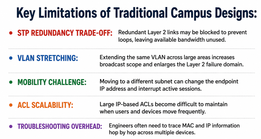
This is where Cisco Software-Defined Access (SD-Access) enters the picture. Cisco SD-Access is not just a new feature or a small upgrade; it is a complete reimagining of how enterprise networks are designed, built, and managed. It moves us away from box-by-box configuration and static, IP-based policies. Instead, it introduces a highly automated, policy-driven architecture that decouples a user’s identity from their physical location on the network. At the very heart of this revolutionary architecture is a protocol that changes everything: VXLAN.
In this blog, we will break down the complexities of Cisco SD-Access, but we will focus primarily on the engine that drives its data plane: Virtual Extensible LAN (VXLAN). We will explore why VXLAN was chosen, how it operates under the hood, and why mastering it is absolutely critical for CCNP professionals, CCIE candidates, and any network engineer looking to future-proof their career.
The Core Problem with Traditional Designs
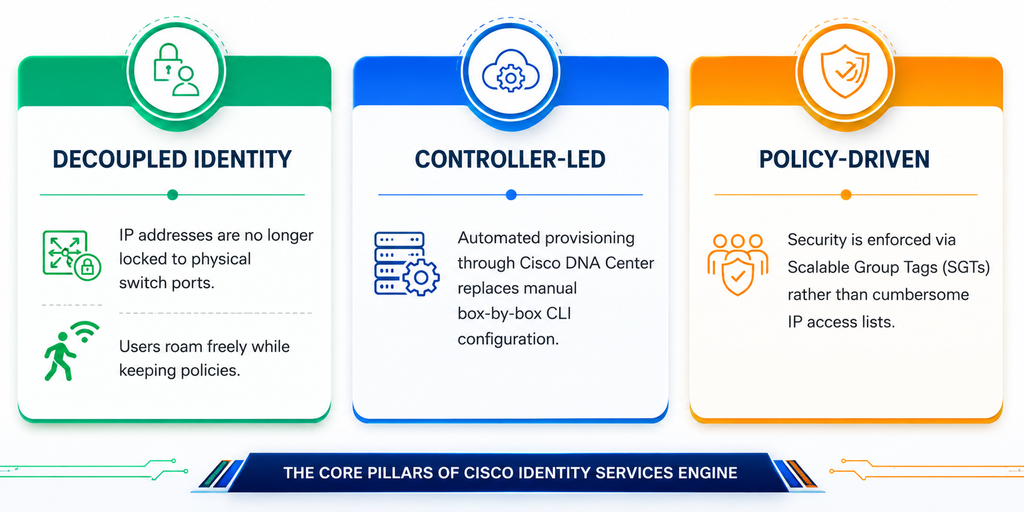
Before we can truly appreciate the brilliance of VXLAN and SD-Access, we must thoroughly understand the limitations of the networks we have been building for the last twenty years. The traditional hierarchical network model Core, Distribution, and Access has served us well, but it relies on technologies that were never designed for the scale and mobility required today.
Let us talk about Spanning Tree Protocol (STP). STP was a necessary evil. Its primary job is to prevent layer 2 loops by blocking redundant links. While this keeps the network from melting down due to broadcast storms, it inherently means that we are wasting up to half of our available bandwidth. We buy expensive fiber links and high-end switches, only to have STP block those links just in case a primary link fails. Furthermore, when a topology change occurs, STP convergence can take precious seconds, causing noticeable disruptions to real-time applications like voice and video.
Then we have the challenge of IP addressing and mobility. In a traditional design, a VLAN is tied to a specific IP subnet, and that subnet is typically localized to a specific distribution block. If an employee moves to a different building, they connect to a different access switch, which places them in a different VLAN, resulting in a new IP address. Any session they had open is dropped. If the business demands that the user keep the same IP address regardless of where they roam, engineers are forced to stretch that VLAN across the core of the network. This breaks the fundamental rules of good network design, creating giant failure domains.
Security is another monumental challenge. In traditional networks, we enforce security using Access Control Lists (ACLs). ACLs are based on IP addresses. When a network has thousands of devices, maintaining these ACLs becomes nearly impossible. If a device moves and gets a new IP address, the security policy must be manually updated. This results in bloated, unmanageable firewall rules and switch ACLs that no one wants to touch for fear of breaking something critical.
Network engineers spend countless hours troubleshooting these rigid architectures. When a problem occurs, they must trace MAC addresses and IP addresses hop-by-hop, logging into multiple switches via CLI to figure out where a packet was dropped. The industry desperately needed a way to build a loop-free, highly scalable, and fully mobile network without the baggage of Spanning Tree and stretched VLANs. The answer was to separate the physical network from the logical network. We needed an overlay.
Introducing Cisco SD-Access
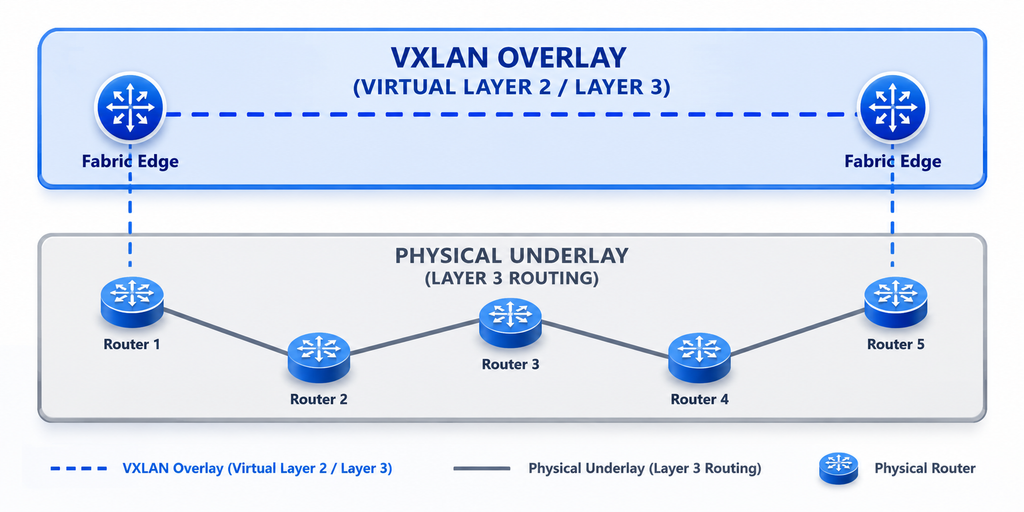
Cisco SD-Access solves the problems of traditional networking by splitting the network into two distinct layers: the Underlay and the Overlay. This separation is the absolute key to understanding modern network fabrics.
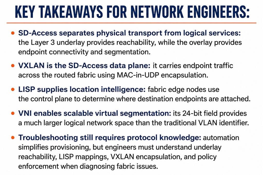
The Underlay is the physical network- the actual cables, routers, and switches. In an SD-Access design, the underlay is built purely on Layer 3 routing. There is no Spanning Tree Protocol, no Layer 2 links between switches, and no stretched VLANs. Every link between every switch is a routed Layer 3 point-to-point connection. We typically use a robust routing protocol like IS-IS or OSPF to ensure that every device in the network knows how to reach the loopback address of every other device. Because it is purely Layer 3, all links are active and forwarding. We achieve Equal Cost Multi-Path (ECMP) routing, meaning we use 100% of our available bandwidth. The underlay is incredibly stable, fast, and simple. Its only job is to provide IP connectivity between network devices.
However, endpoints (like laptops and printers) still need Layer 2 connectivity, and they still need to roam. This is where the Overlay comes in. The Overlay is a virtual network built on top of the physical underlay. It creates virtual tunnels between the edge switches. When an endpoint sends a standard Ethernet frame into the network, the edge switch takes that frame, wraps it in a new header, and sends it across the Layer 3 underlay to the correct destination switch. The destination switch unwraps it and delivers it to the endpoint.
By using an overlay, the endpoints are completely unaware of the complex Layer 3 routing happening in the physical network. As far as the laptop is concerned, it is just plugged into a giant, campus-wide Layer 2 switch. This allows us to keep the same IP address and VLAN anywhere on the campus without actually stretching VLANs in the physical network.
To make this overlay work, Cisco SD-Access uses two primary protocols.
- For the Control Plane- the “brains” that keeps track of where every device is located- it uses LISP (Locator/ID Separation Protocol).
- But for the Data Plane- the actual “muscle” that encapsulates the traffic and moves it across the network- it uses VXLAN.
Understanding how this data plane operates is crucial for any network professional.
Underlay, overlay, and protocol roles at a glance:
- Underlay: the physical Layer 3 transport network that provides IP reachability between fabric nodes and can use ECMP across active routed paths.
- Overlay: the logical network built over the underlay that carries endpoint connectivity without physically stretching VLANs across the campus.
- LISP: the SD-Access control-plane mechanism used to learn and resolve endpoint location information.
- VXLAN: the data-plane encapsulation used to carry endpoint traffic between fabric edge nodes.
The Star of the Show: Understanding VXLAN
Now we arrive at the core objective of our exploration: Understanding Virtual Extensible LAN (VXLAN). VXLAN is an industry-standard encapsulation protocol. Simply put, it is a tunneling mechanism that takes a standard Layer 2 Ethernet frame, wraps it inside a UDP packet, and routes it across a Layer 3 network. This is often referred to as “MAC-in-UDP” encapsulation.
Why was VXLAN created in the first place? It was originally developed for massive data centers to overcome the limitations of the traditional 802.1Q VLAN tag. A standard VLAN tag is 12 bits long, which means a network can only support a theoretical maximum of 4,096 VLANs. In a massive cloud data center hosting thousands of different tenants, 4,000 VLANs are simply not enough. VXLAN introduces a 24-bit identifier known as the VXLAN Network Identifier (VNI). This 24-bit space allows for over 16 million unique virtual networks. While an enterprise campus might not need 16 million networks, this massive scale provides incredible flexibility for network segmentation and multi-tenancy.
Key VXLAN technical details:
- Encapsulation model: VXLAN carries an original Ethernet frame across a Layer 3 network using MAC-in-UDP encapsulation.
- VLAN ID: traditional 802.1Q uses a 12-bit identifier, giving a theoretical space of 4,096 VLAN values.
- VNI: VXLAN uses a 24-bit VXLAN Network Identifier, providing more than 16 million possible identifiers.
- VTEP: The VXLAN Tunnel Endpoint performs encapsulation and decapsulation at the edge of the VXLAN tunnel.
- Standard destination port: VXLAN uses UDP port 4789.
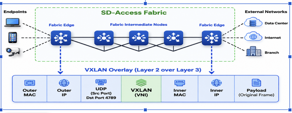
Let us break down exactly what happens when a packet enters a VXLAN environment. Imagine a user’s laptop sends a standard data Frame. This frame contains a source MAC address, a destination MAC address, an IP header, and the data payload. When this frame hits the first switch in the SD-Access fabric (the Fabric Edge node), the switch does not simply forward it as usual. Instead, it acts as a VTEP (VXLAN Tunnel End Point).
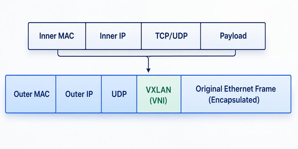
The VTEP takes the entire original frame from the laptop and wraps it in a new VXLAN header. Inside this VXLAN header, the switch inserts the all-important VNI, which identifies which virtual network this packet belongs to. Next, it wraps this VXLAN header inside a standard UDP header. Finally, it wraps all of that into an outer IP header and an outer MAC header. The outer IP addresses belong to the physical underlay network-specifically, the loopback address of the source switch and the loopback address of the destination switch.
Once this massive, encapsulated packet is built, the switch sends it out into the Layer 3 underlay. The intermediate core switches in the network do not look at the user’s data, the user’s IP address, or the user’s MAC address. All they see is an outer IP packet destined for another switch. They route it across the network at lightning speed using standard routing protocols.
When the packet finally arrives at the destination Fabric Edge switch, the reverse process happens. The receiving switch strips off the outer MAC header, the outer IP header, the UDP header, and the VXLAN header. It looks at the original, untouched inner Ethernet frame and delivers it to the final destination endpoint. The endpoints have no idea that their data was just wrapped up, shipped across a routed network, and unpacked.
VXLAN encapsulation and forwarding flow:
- Original frame: the endpoint sends a normal Ethernet frame containing its original Layer 2 and Layer 3 information.
- VXLAN header: the ingress VTEP adds the VXLAN header and inserts the VNI that identifies the virtual network.
- UDP and outer headers: UDP, outer IP, and outer MAC headers are added for transport through the underlay.
- Underlay forwarding: intermediate devices route the packet using the outer IP information rather than the endpoint addresses inside the tunnel.
- Decapsulation: the destination VTEP removes the outer headers and forwards the original Ethernet frame to the endpoint.
| Key Concept for Network Engineers VXLAN uses UDP as its transport, and the UDP fields also help the routed underlay distribute different flows across multiple equal-cost paths. The values worth remembering are: • Destination UDP port: 4789 is the standard VXLAN destination port. • Source UDP port: it is dynamically derived, commonly from a hash of the inner flow. • Why it matters: different source-port values give the underlay additional entropy for ECMP load balancing. |
This MAC-in-UDP encapsulation is genius for several reasons. By using UDP, VXLAN allows the underlay network routers to look at the UDP source ports and use them for load balancing. This ensures that traffic is perfectly distributed across all available physical links, maximizing network efficiency. It eliminates the need for the Spanning Tree Protocol while still providing native Layer 2 connectivity between devices.
How LISP and VXLAN Work Together in SD-Access
To fully grasp SD-Access, you must understand that VXLAN does not work alone. VXLAN is a data plane technology & it handles the actual moving of the packets. But how does the source switch know where to send the VXLAN tunnel? How does it know which switch is currently hosting the destination IP address? If we used traditional flooding and learning (like standard Ethernet does with broadcast ARPs), the network would collapse under its own weight. We need a control plane. In Cisco SD-Access, that control plane is LISP (Locator/ID Separation Protocol).
LISP operates very much like the Domain Name System (DNS) of the internet, but for IP addresses and MAC addresses. Let us use a simple human analogy. Imagine you want to send a letter to your friend, John. John’s identity (his name) does not change, but his location (his physical address) might change if he moves to a new city. In the network world, an endpoint’s IP address is its Identity, and the switch it is connected to is its Location.
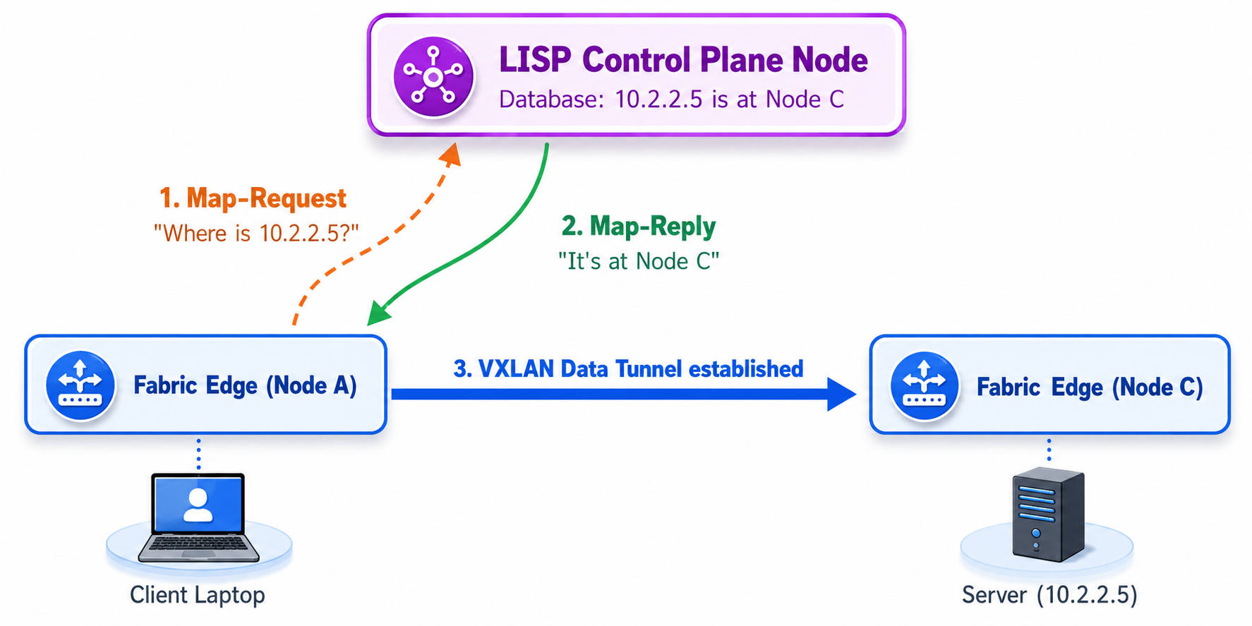
In an SD-Access network, there is a central database called the Control Plane Node (often running on a robust router or switch). When a new device connects to a Fabric Edge switch, the switch registers that device with the Control Plane Node. It essentially says, “I am Switch A, and I am currently hosting the endpoint with IP 10.1.1.5.”
Now, let us trace a packet. When a user’s laptop wants to talk to a server, it sends the packet to its local Fabric Edge switch. The edge switch looks at the destination IP address, but it does not have a traditional routing table entry for it. Instead, the switch sends a query to the LISP Control Plane Node: “Who is hosting the server with IP 10.2.2.5?”
The Control Plane Node checks its database and replies: “That server is currently located at Fabric Edge Switch C.” Armed with this information, the local switch now knows exactly what to do. It takes the user’s data packet, encapsulates it in a VXLAN header, and sets the outer destination IP address to the loopback address of Switch C. The packet is then blasted across the physical underlay.
This dynamic combination of LISP and VXLAN is what makes SD-Access so powerful. LISP eliminates the need for broadcasting ARPs across the network to find devices, completely silencing the chatter that normally degrades network performance. VXLAN provides the secure, flexible tunnel to transport the data once the location is known. Together, they create an incredibly efficient, scalable, and robust architecture.

LISP and VXLAN: do not confuse their roles:
• LISP = control plane: it maintains endpoint-to-location mappings and answers lookup requests from fabric edge nodes.
• VXLAN = data plane: it encapsulates and transports the actual user traffic after the destination location is known.
• Typical sequence: the source edge resolves the destination through LISP, then sends the traffic through a VXLAN tunnel toward the destination edge.
• Architecture comparison: Cisco SD-Access uses LISP as its control plane, while many data-center VXLAN fabrics use BGP EVPN.
Conclusion and Future Outlook
For CCNP professionals, CCIE candidates, and working network engineers, the transition from traditional networking to SD-Access can seem daunting. There are new terminologies, new protocols, and the complexity of managing underlays and overlays. However, understanding the core engine- VXLAN-demystifies much of this architecture.
By leveraging VXLAN as the data plane, Cisco SD-Access frees the network from the physical constraints of Spanning Tree, rigid VLANs, and IP-based ACLs. It provides a robust, scalable, and automated fabric where identity is decoupled from location. While an orchestrator like Cisco DNA Center hides much of the CLI configuration and handles the automation, the true networking professional must understand what is happening under the hood. When troubleshooting complex fabric issues, knowing how a MAC-in-UDP packet traverses a Layer 3 underlay and how LISP resolves the destination is what separates an average administrator from an expert engineer.
The future of enterprise networking is heavily automated, policy-driven, and built entirely on overlay technologies. VXLAN is no longer just a data center buzzword; it is the fundamental building block of the modern campus network. Embracing this architecture not only ensures the reliability and security of your enterprise infrastructure but also ensures that your skills remain highly relevant in a rapidly evolving technological landscape.
Check 100% Job Guarantee Courses
- CCIE Enterprise Infrastructure V1.0/R&S Training in India
- CCIE Security V6.1 Course
- Cyber Security & Network Security Course
- Cloud Security + Network Security Expert
Frequently Asked Questions
Cisco SD-Access addresses limitations such as VLAN stretching, large Layer 2 failure domains, STP dependency, IP-based ACL scalability, and difficult endpoint mobility. It separates the physical Layer 3 underlay from the logical overlay, allowing endpoint connectivity and policies to remain independent of the physical network location.
The underlay is the physical Layer 3 network that provides IP reachability between fabric nodes. It uses routed links and can use ECMP across multiple active paths. The overlay is a virtual network built over this underlay that provides endpoint connectivity without physically stretching VLANs across the campus.
VXLAN provides the data-plane encapsulation for SD-Access. It takes the original Ethernet frame, encapsulates it using a VXLAN header, UDP, and outer IP/MAC headers, and transports it across the Layer 3 underlay. This allows Layer 2 endpoint connectivity to operate across a routed infrastructure without physically extending VLANs.
A VXLAN Network Identifier (VNI) is a 24-bit identifier carried in the VXLAN header. It identifies the virtual network or segment to which the traffic belongs. Unlike the 12-bit VLAN identifier, which provides a theoretical space of 4,096 values, the VNI provides more than 16 million possible identifiers, enabling much greater segmentation and scalability.
LISP provides the control plane, maintaining endpoint-to-location mappings and helping a Fabric Edge determine where the destination endpoint is located. VXLAN provides the data plane, encapsulating and transporting the actual user traffic toward that destination. In a typical flow, the source Fabric Edge resolves the destination location through LISP and then sends the traffic through a VXLAN tunnel to the destination Fabric Edge.