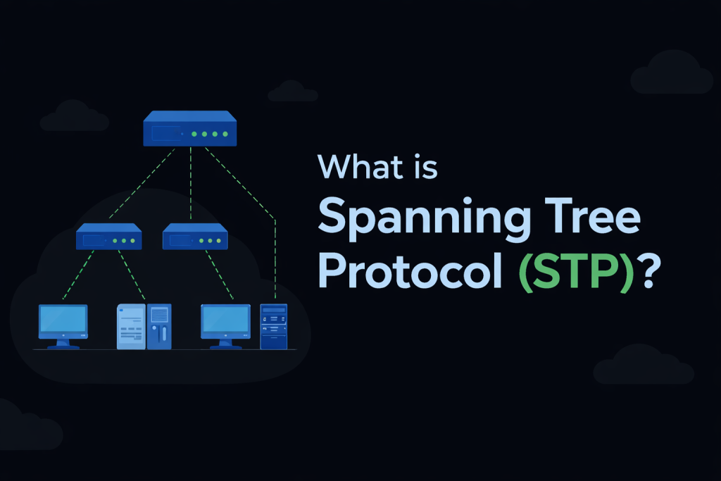
Spanning Tree Protocol (STP) is a Layer 2 protocol that is enabled by default on network switches. It was developed to prevent loops in Local Area Networks (LANs) that contain redundant links. STP protects the Layer 2 network by intelligently blocking paths while keeping them available as backups. These blocked links automatically become active if the primary forwarding path fails, ensuring network stability and reliability.
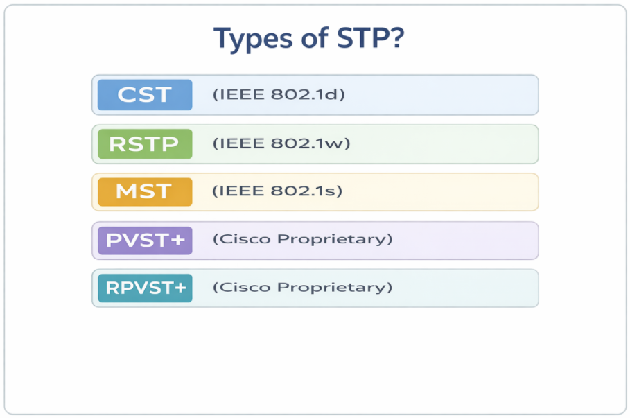
Types of STP?
What is layer 2 Loop and why is it Dangerous in redundant LAN networks?
Broadcast frames combined with loops in a redundant Layer 2 network can be extremely dangerous. Let’s understand this behavior using the following example.
Assume that neither switch is running Spanning Tree Protocol (STP). Host A sends a frame with a broadcast MAC address as the destination FFFF: FFFF: FFFF (Step 1).
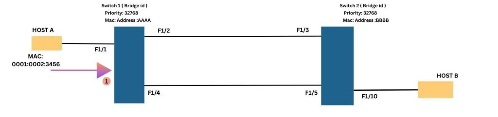
The frame arrives at port F1/1 on Switch-1. Switch 1 then floods the broadcast frame out of ports F1/2 and F1/4 (Step 2). The frame is received by Switch 2 on ports F1/3 and F1/5 (Step 3).
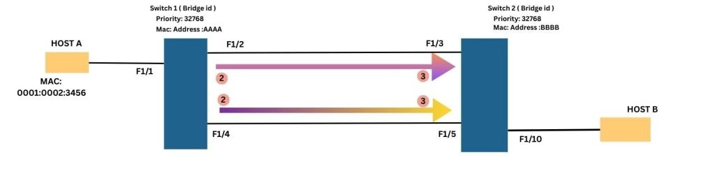
Since it is a broadcast frame, Switch 2 floods it out of all other ports including F1/3 and F1/5 (Step 4). As a result, the same frame is received back by Switch 1 on ports F1/2 and F1/4 (Step 5).
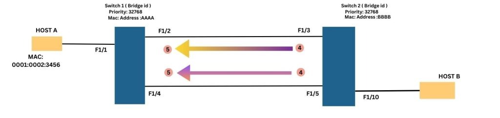
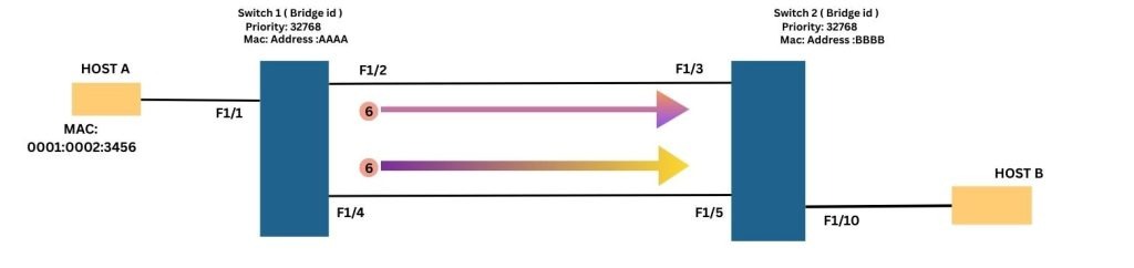
Upon receiving the frame again, Switch 1 repeats the same flooding process and forwards the frame out of ports F1/2 and F1/4 once more (Step 6). This process continues indefinitely, causing the broadcast frame to loop continuously between the switches. From this behavior, it is clear that a layer 2 switching loop has formed in the redundant Layer 2 network.
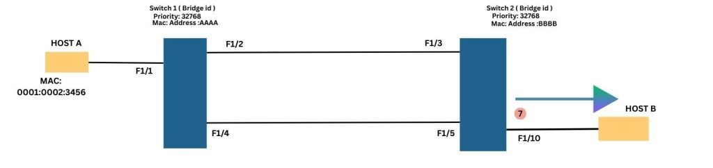
Additionally, notice that the broadcast frame received on ports F1/3 and F1/5 of Switch 2 is also forwarded out of port F1/10 (Step 7), where Host B is connected.
In conclusion, without Spanning Tree Protocol (STP), broadcast frames can loop endlessly within a Layer 2 network, leading to severe network congestion and instability.
Understanding the Limitations of Loops in Redundant Layer 2 Networks?
Switching loops introduce several limitations in a layer 2 network. Some of the most common issues are outlined below:
Broadcast Storms: Broadcast frames continuously loop through the network, generating excessive traffic. This can severely degrade network performance and, in extreme cases, leads to a complete network outage.
High CPU Utilization on Switches: Switches are forced to process the same frames repeatedly, which significantly increases CPU utilization. As a result, switch performance may degrade or become unresponsive.
MAC Address Table Instability: The same MAC address may be learned on multiple ports due to looping frames. This causes constant updates to the MAC address table, leading to instability and unpredictable forwarding behavior.
Multiple Frame Copies Received by Hosts: Hosts may receive duplicate copies of the same frame as it is retransmitted repeatedly through the loop, resulting in unnecessary processing.
Let’s deep dive into the Spanning Tree Protocol
First, the Spanning Tree Protocol (STP) selects one switch to serve as the Root Bridge. It then constructs a loop-free tree by placing redundant links into a blocking state. If an active link fails, these blocked links can transition to a forwarding state to maintain network connectivity.
Initially, all switches exchange Bridge Protocol Data Unit (BPDU) messages to elect the Root Bridge. Once the election process is complete, each switch determines the optimal path to the Root Bridge. This process ensures a single, loop-free path for sending and receiving frames.
The initial STP process can be explained in three simple steps:
- Elect one switch as the Root Bridge
- Select the Root Port on each non-root switch
- Select the Designated Port for each network segment
Four-Step STP Decision Sequence:
When creating a loop-free logical topology, Spanning Tree protocol always follow the same four-step decision sequence:
- Lowest Root Bridge-ID
- Lowest Path Cost to the Root Bridge
- Lowest Sender Bridge-ID
- Lowest Port ID, which is determined by:
- Lowest Sender Port Priority
- Lowest Sender Port Number
How STP Elects the Root Bridge: A Step-by-Step Guide
All switches must first elect a single Root Bridge by identifying the switch with the lowest Bridge ID (BID). The switch with the lowest BID wins the election process often referred to as a “Root War.”
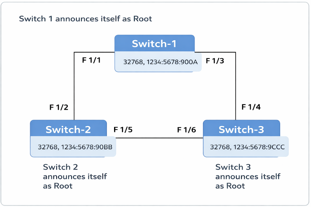
During this Root War, all switches exchange “Configuration BPDUs” to participate in the Root Bridge election. The election is based on the Bridge ID, which is 8 bytes in size and consists of two components: Priority (2 bytes) and Base MAC Address (6 bytes). By default, the switch priority is 32,768.
Note: In Cisco proprietary flavors of STP, the priority can be adjusted from 0 to 61,440 in increments of 4,096.
At one point in the election, Switch 1 may continuously claim itself as the Root Bridge. Meanwhile, Switch 2 and Switch 3 stop their own announcements and start acting as non-root switches.
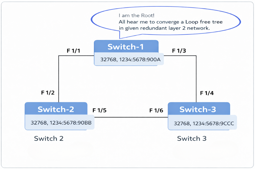
This is made possible by the exchange of Configuration BPDUs, which initially occurs among all switches during the Root Bridge election and subsequently originates from the elected Root Bridge to maintain network stability.
Inside a Configuration BPDU: A Complete Breakdown:
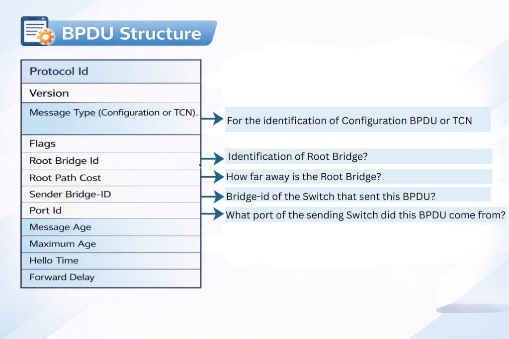
Note: Always remember that the Root BID refers to the Bridge ID of the current Root Bridge, while the Sender BID represents the Bridge ID of the local switch relaying the configuration BPDU.
Understanding Root Port Election:
After the Root Bridge has been elected, each non-root switch proceed to select its Root Port. Every non-root switch elects one port as its Root Port that provides the shortest path to the Root Bridge. Switches follow a sequential set of criteria to determine port roles.
To identify the best path, switches use the concept of Root Path Cost, which measures the cumulative cost of all links from the non-root switch to the Root Bridge. The port with the lowest total Root Path Cost becomes the Root Port.
If multiple paths have the same Root Path Cost, the election uses tie-breakers in order of lowest sender Bridge ID, followed by lowest sender Port ID.
Example:
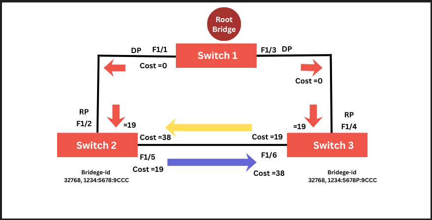
Switch 1 sends a BPDU with a Root Path Cost of 0. Switch 2 receives this BPDU and adds the cost of its incoming port (F1/2) to the Root Path Cost: 0 + 19 = 19. Switch 2 then advertises this updated cost (19) out of its port F1/5.
Switch 3 receives this BPDU on port F1/6, adding its link cost of 19 to the received cost of 19, resulting in a total Root Path Cost of 38. At the same time, Switch 3 also receives a BPDU from Switch 1 on port F1/4 with a Root Path Cost of 0. Adding the link cost (19) gives a total cost of 19.
Switch 3 now has two possible paths to the Root Bridge:
- Via F1/4 with a Root Path Cost of 19
- Via F1/6 with a Root Path Cost of 38
Since F1/4 has the lower root path cost, Switch 3 elects it as the Root Port and advertises a Root Path Cost of 19 to any downstream switches. Similarly, Switch 2 also follow the same process to elect F1/2 as its Root Port.
Note: Always remember that the Root Path Cost is incremented when a BPDU is received, not when it is forwarded out of a switch port.
Understanding Designated Port Election:
The loop-free topology convergence is completed after the election of the Designated Port (DP). Each network segment (link) has one designated port, which is selected based on the lowest advertised Root Path Cost on that segment. In the given topology, there are three segments:
- The segment between Switch 1 and Switch 2.
- The segment between Switch 1 and Switch 3.
- The segment between Switch 2 and Switch 3.
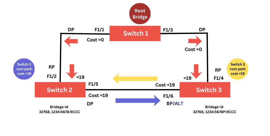
Understanding the STP election process is straightforward for segments 1 and 2. On both segments, Switch 1 advertises the lowest root path cost consistently, so ports F1/1 and F1/3 on Switch 1 become the Designated Ports.
Now, let’s focus on the segment between Switch 2 and Switch 3. Both Switch 2’s port F1/5 and Switch 3’s port F1/6 advertise a Root Path Cost of 19, resulting in a tie for this segment. When a tie occurs during port role election, STP follows a sequence of tie-breakers:
- Lowest Root Path cost
- Lowest Sender Bridge-ID
- Lowest Port ID
- Lowest Sender Port Priority
- Lowest Sender Port Number
In this scenario, Switch 2 has the lower Bridge ID compared to Switch 3. Therefore, port F1/5 on Switch 2 is elected as the Designated Port, while port F1/6 on Switch 3 becomes the non-designated port, often referred to as the blocked or alternate port.
STP Timers: The explanation of the timers is as follows:
- Hello Timer: This timer is used to determine how often the root bridge sends configuration BPDUs. By default interval is 2 seconds.
- Forward Delay Timer: This timer determines how long to stay in the listening state before learning, and in the learning state before forwarding. By default, it is 15 sec’s.
- Maximum Age Timer: This timer defines that how long a switch is going to store the best BPDU if it stops receiving BPDUs. By default, it is 20 sec’s.

STP States: STP transitions each port through several states from Disabled to Blocking, Listening, Learning and Forwarding. At last, Forwarding and Blocking are the only two states commonly seen in a converged STP network.
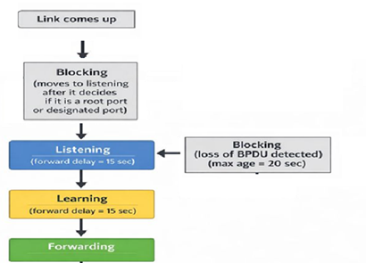
Note: Amber color for both Listening & Learning state.
Root Bridge Placement: Key Design Principles for Enterprise Networks
In the Cisco Hierarchical Model (which consists of the Access, Distribution and Core layers), placing the Root Bridge in the Spanning Tree Protocol (STP) is a design decision, and should never be left to chance.
Cisco strongly recommends positioning the Root Bridge at the Distribution layer rather than the Access layer. The Distribution layer is ideal because it interconnects the Access switches to the Core, has high-speed links, offers higher processing capacity, and supports predictable traffic flow.
By making the Distribution switch the Root Bridge, all Access-layer switches forward traffic upward toward Distribution layer by creating loop-free paths. This approach also aligns the STP topology with the Layer 3 boundary, where routing, ACLs, and QoS policies are implemented.
What happens if the Root Bridge is placed at the Access layer?
Placing the Root Bridge at the Access layer is considered poor design and can lead to several issues. Since Access switches are generally lower-capacity devices connected through uplinks to Distribution switches, electing an Access switch as Root Bridge forces traffic to follow suboptimal paths. This results in increased latency, inefficient bandwidth utilization, and more complex troubleshooting.